Ron
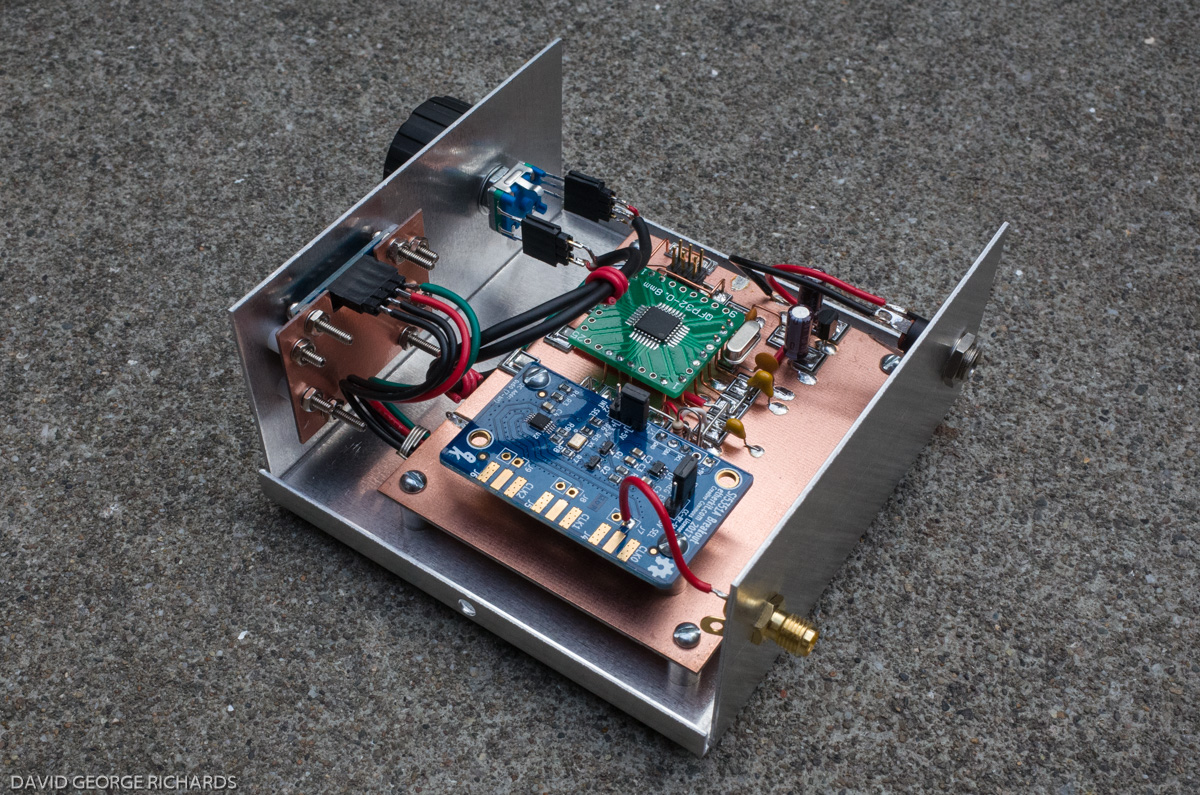
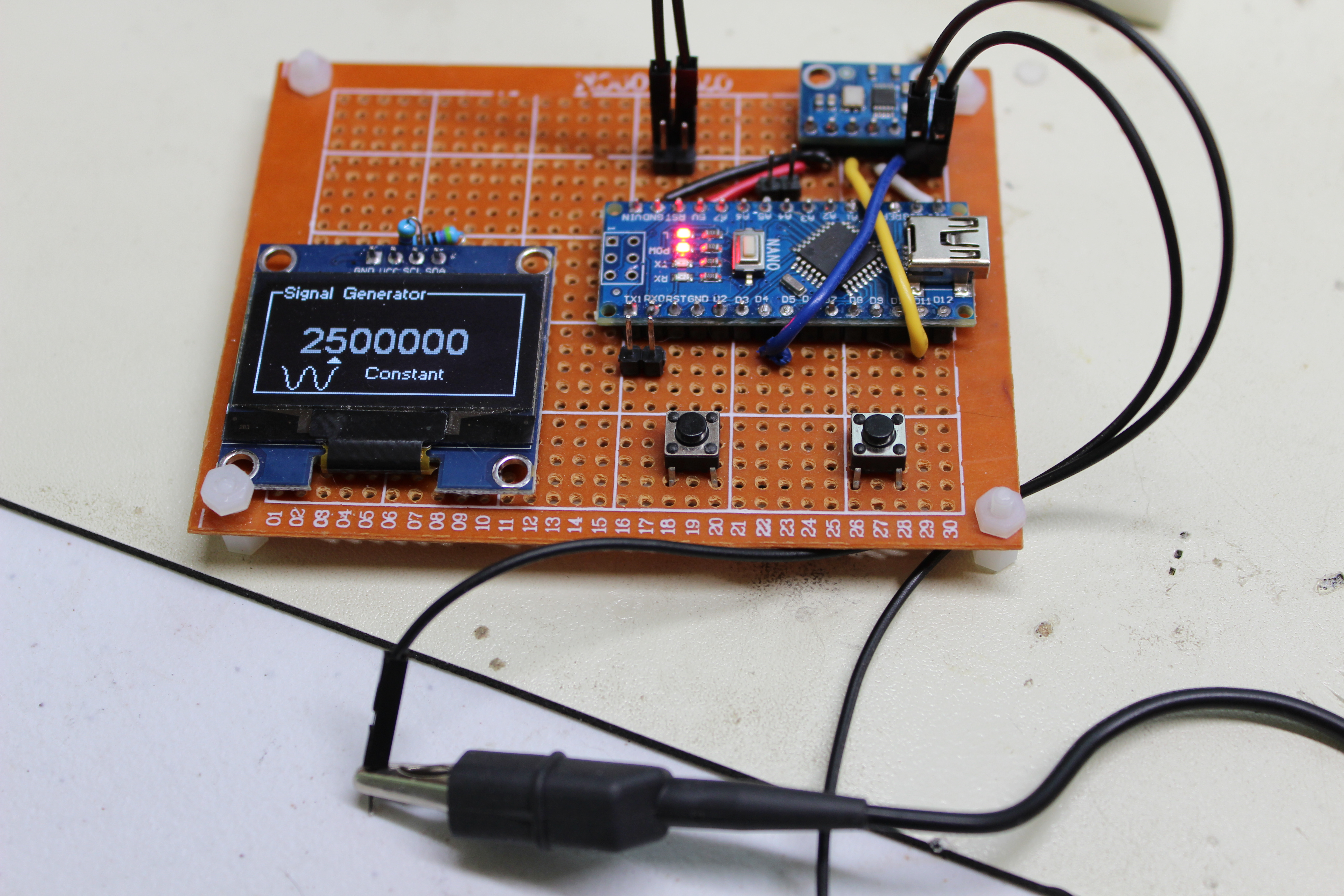
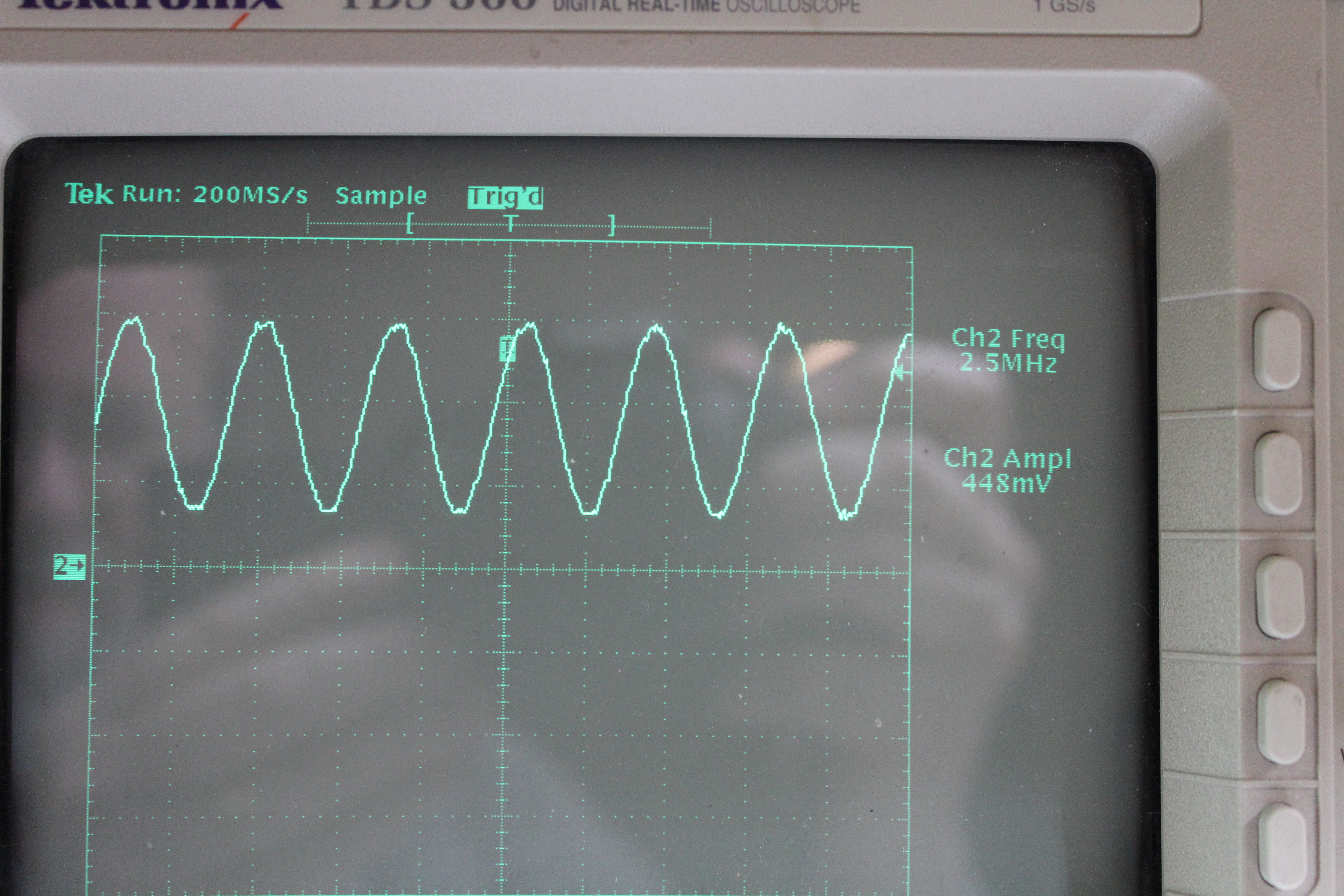
Signal Generator
Solar Data
My uBitx v5 Build
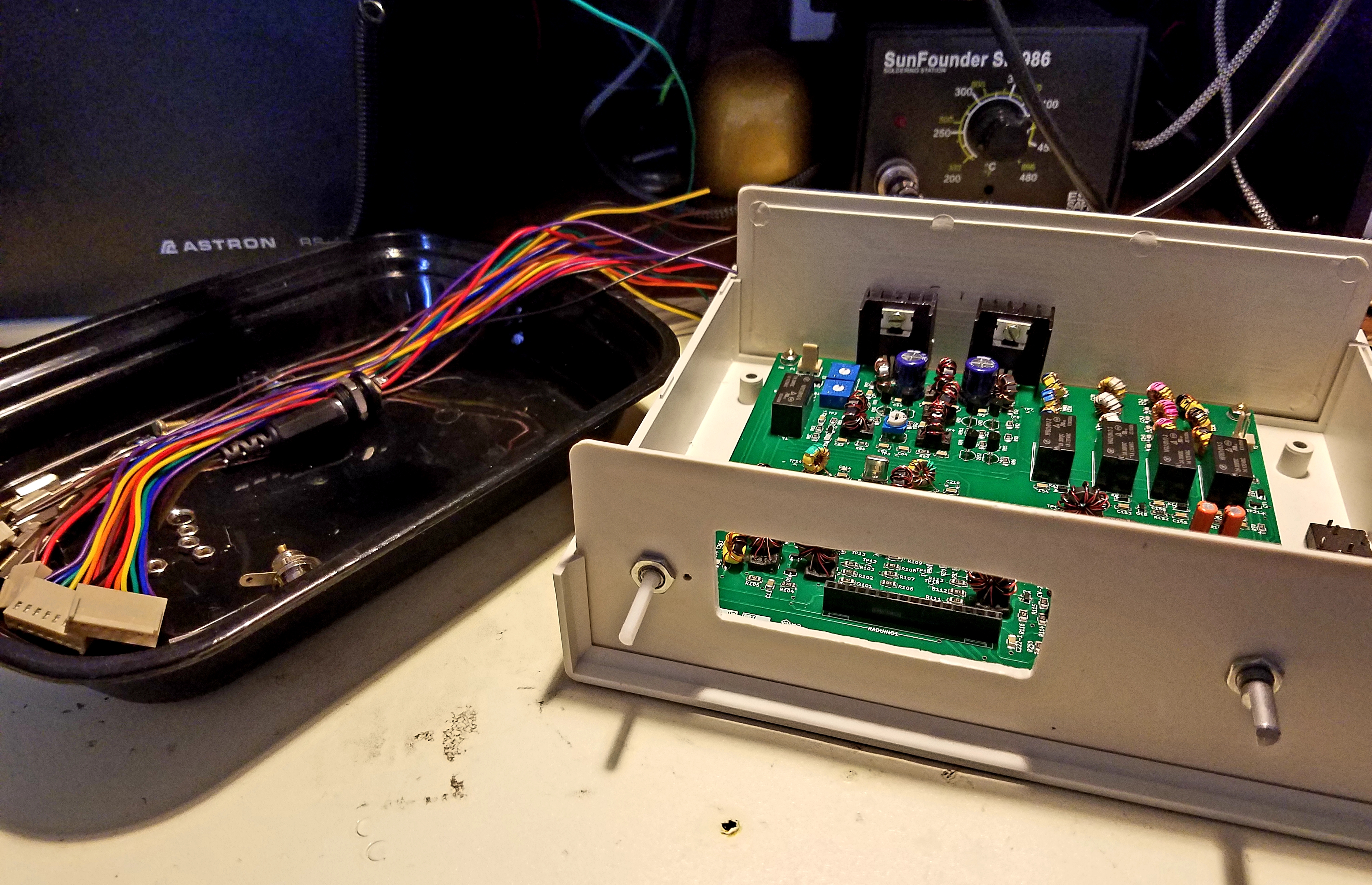
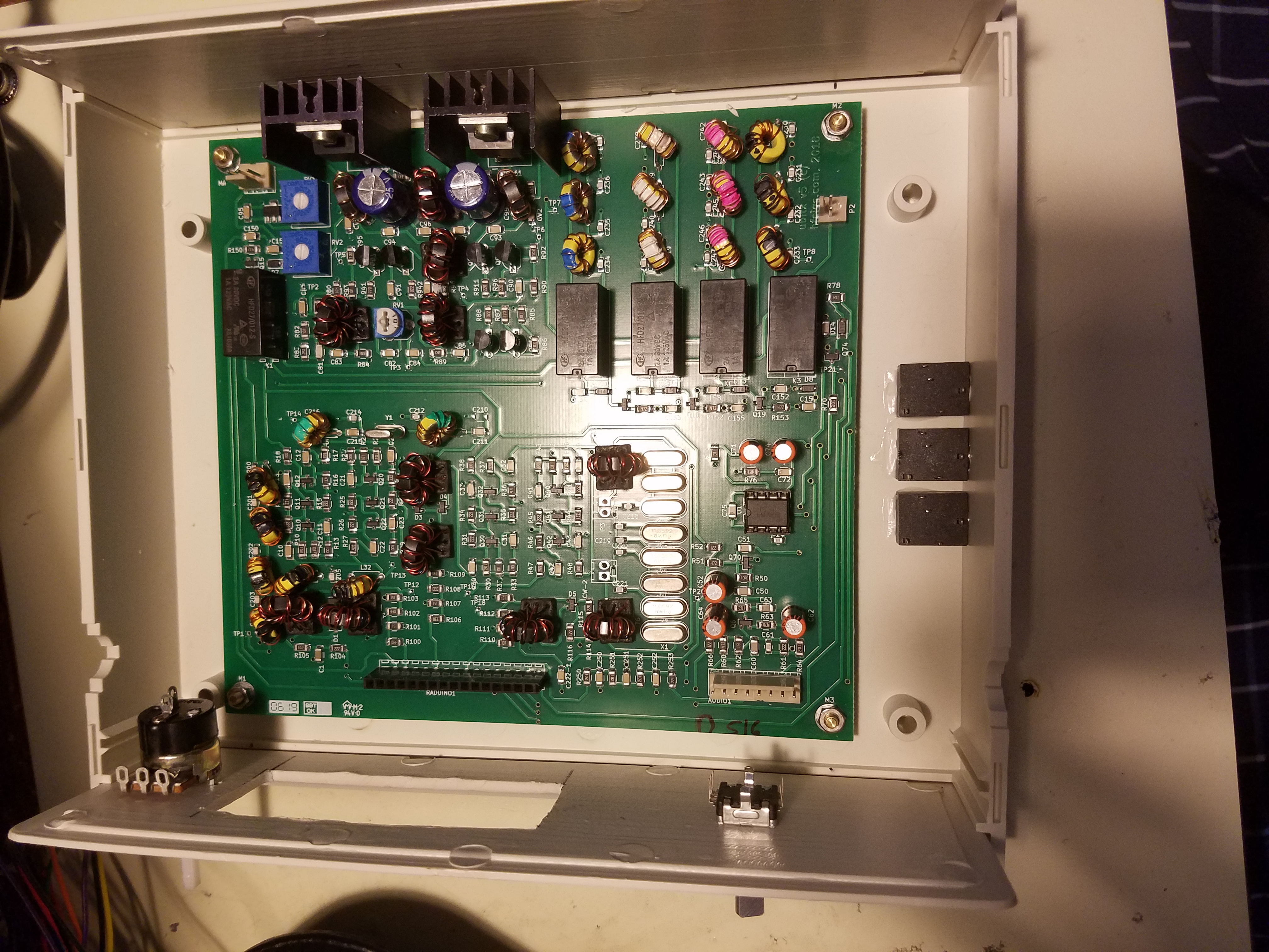
Starting my uBitx build. I am using an EF01 case for my unit.
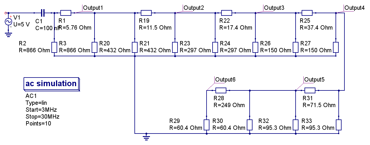
Schematic of Step Attenuator
Searched online to find some schematics of step attenuators and then edited schematic into QUCS.
Simulator result
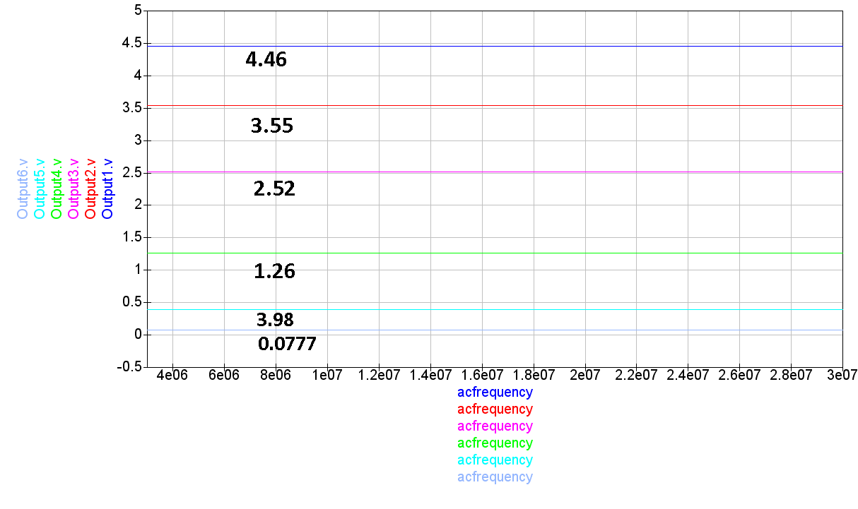
DB
| Volts | Expected DB | Calc DB |
| 5 | ||
| 4.46 | 1 | -0.99 |
| 3.55 | 3 | -2.97 |
| 2.52 | 6 | -5.95 |
| 1.26 | 12 | -11.97 |
| 0.403 | 22 | -21.87 |
| 0.0675 | 42 | -37.39 |
The +20 db step is off quite a bit.
Make a Programming Cable for a Yaesu FT-4X
I referenced this video to modify a Baofeng cable to make a programming cable for a Yaesu FT-4X.
- Pulled 3.5 mm audio pin out of cable

- Open case at USB end of the cable gently with small screwdriver. Pry at the cable stress relief end.
- Watch this video (Yaesu FT-4X Programming Cable) and dig out the needed diode from your parts stock.
- solder it up

- Test the cable with programming software available at yaesu.com
- Reassemble the case
Building an EU1KY Antenna Analyzer
So I got my Technician license April 2018 and wanted to get started in the amateur radio 2M band. Knowing that I would want to make a good antenna, I figured that I would need an antenna analyzer. I looked at the costs of analyzers on the market and decided to DIY. That’s when I found the EU1KY.
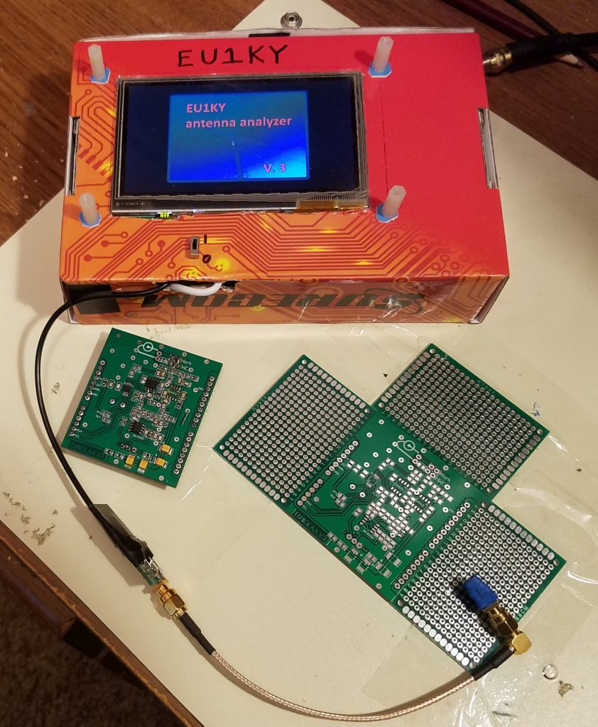
I assembled the analyzer using the required instructions for the EU1KY open source project (EU1KY wiki page) after ordering boards for the RF unit (I have extra boards for sale on my Ebay Site).
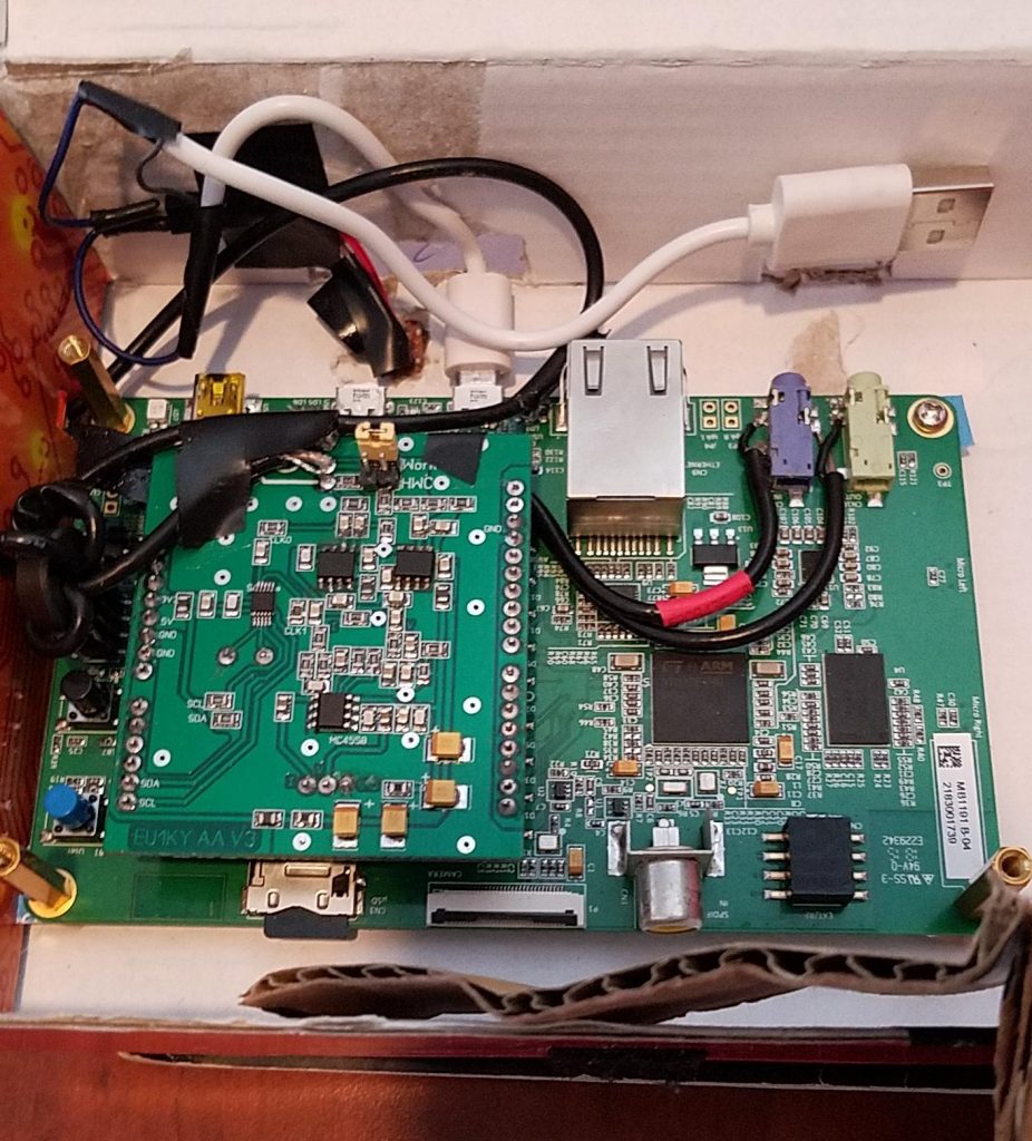
Note: The RF front end board mounts onto an
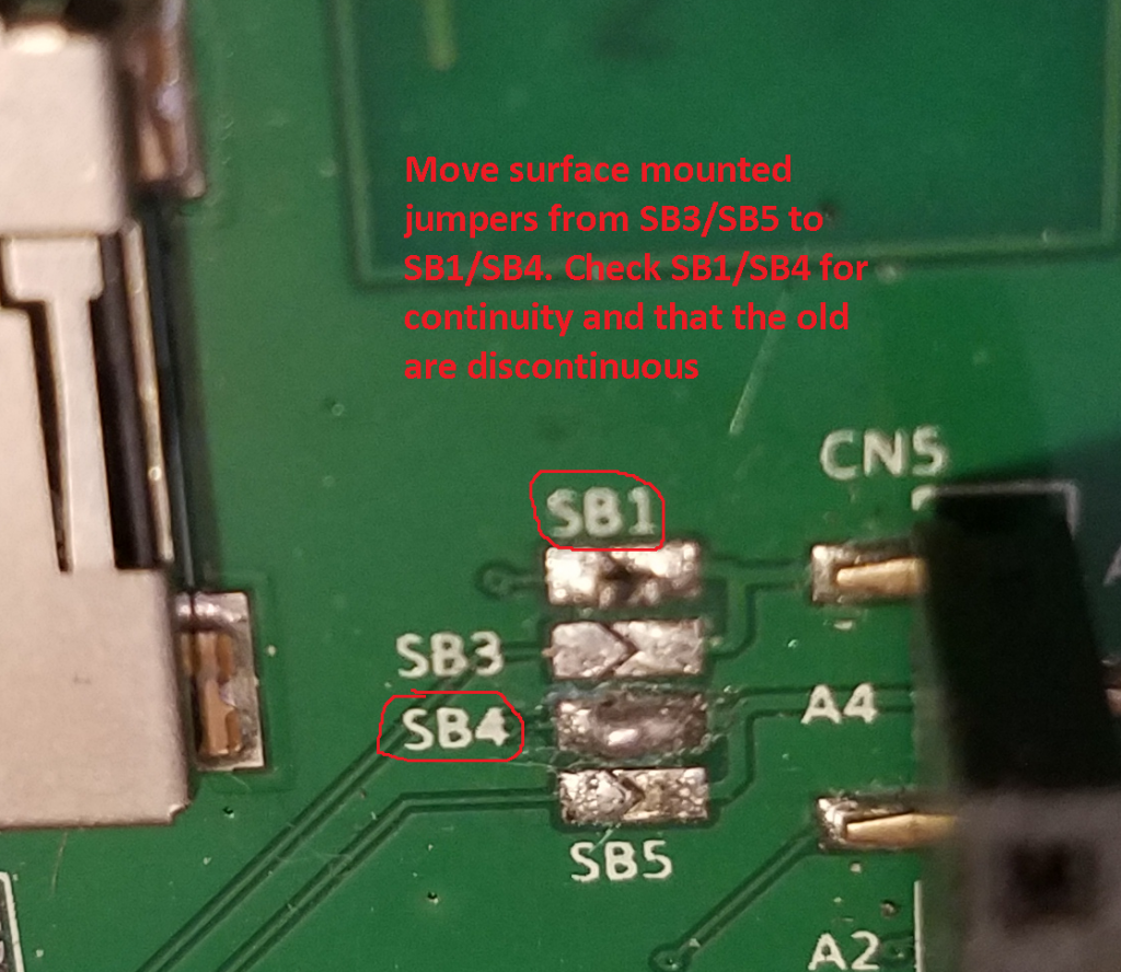
STM32F746G-DISCO Development Board (available from Digikey.com for about $60). Under the connectors for the RF board there are some surface mounted jumpers. The board comes with them soldered onto SB3/SB5. Move them to SB1/SB4 and then check them for continuity. Check that SB3/SB5 are non-continuous.
Connect I, V and Gnd from RF board to blue audio on Discovery board like this.

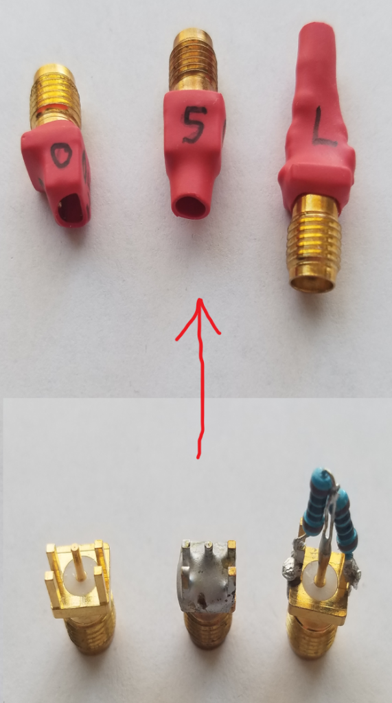
For calibration, an Open/Short/Load (OSL) test kit is needed. I built mine from some spare SMA PCB board components. The 50 Ohm load has two 100 Ohm resistors in parallel and can be made more attractive by using 0805 SMD resistors. You could even do three 150 Ohm resistors in parallel to achieve the 50 Ohm target value.
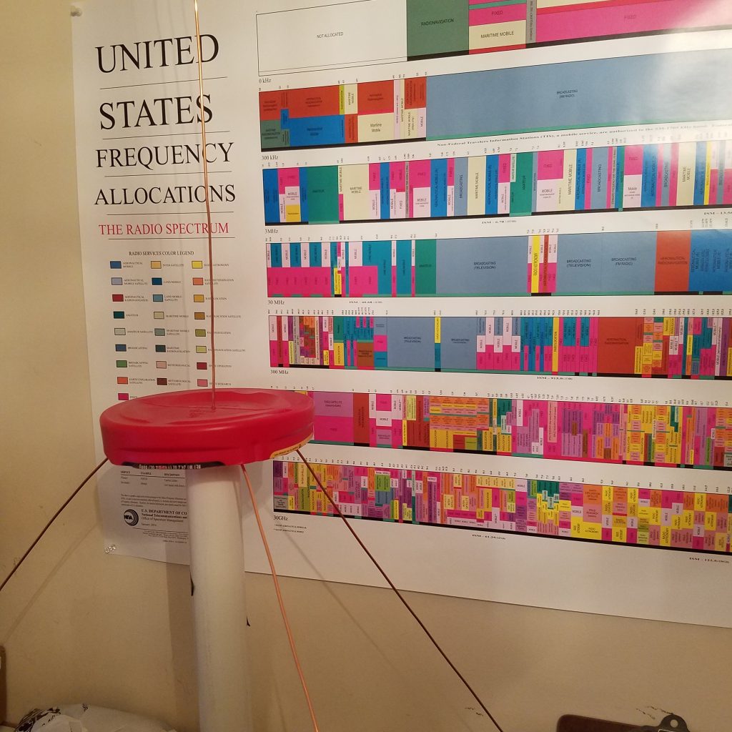
Afterwards, I built a 2 meter ground plane antenna.
Measurment
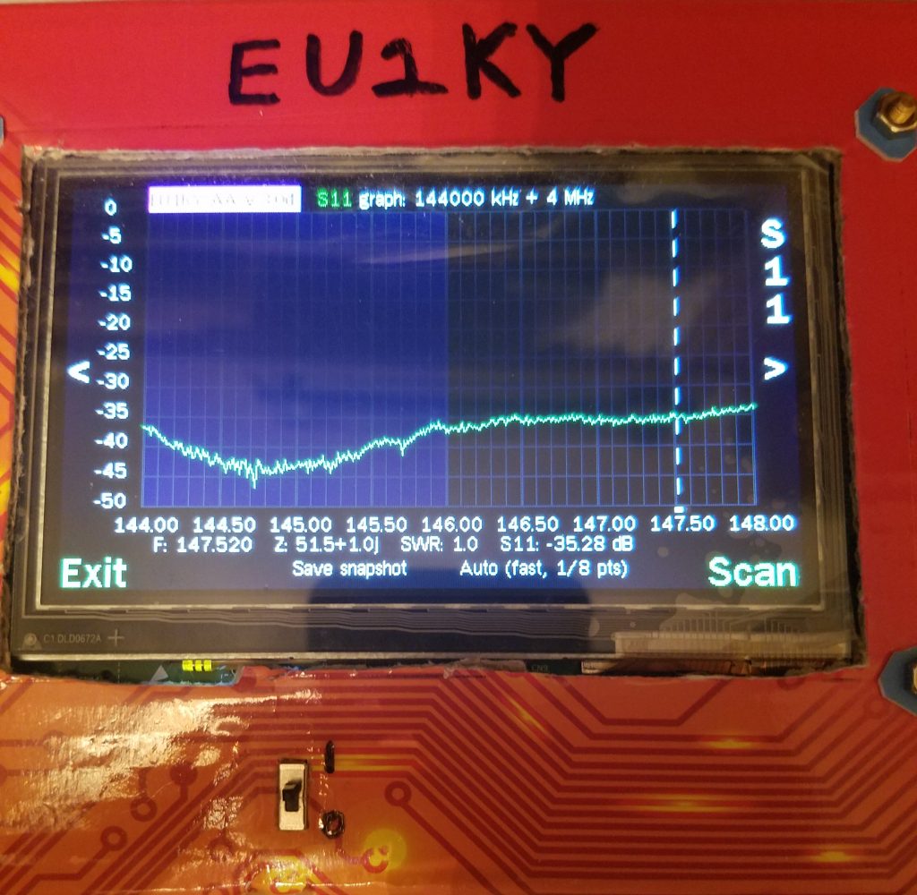
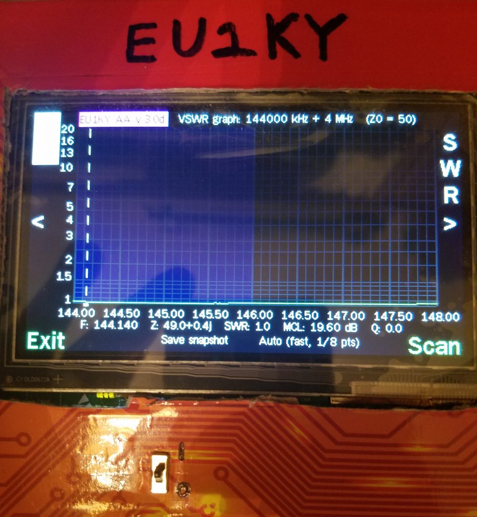
Used analyzer to scan 144Mhz – 148 Mhz …
The results:
I welcome any discussion on this project. Just add comments below or email me at my arrl.net address (callsign ke0rje).


